
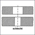
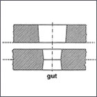
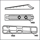
1. Filling of the cavity BWall thickness influences the feedstock flow inhomogeneous form filling, recognizable from the timelines Bottom: homogeneous form filling due to increased wall thickness towards the corners |
| ||||||||||||||
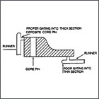
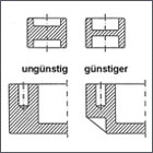
2. Selection of the gate position A gate position close to thick-walled areas: Due to the quick cooling of the feedstock, |
| ||||||||||||||
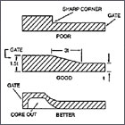
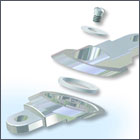
3. Draft angles for ejection MIM green parts exhibit less strengthand less shrinkage than usual polymers. Thus they need large size ejectors and large draft angles. Draft angle > 1° Ejectors: 4-6 times larger compared to plastic injection moulding |
| ||||||||||||||
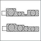
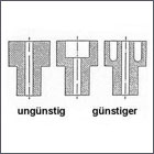
4. Adjusting wall thickness Goal:Uniform wall thickness for the complete part wall thickness: max. 25 mm; good: 1-10 mm; better: 1-5 mm |
| ||||||||||||||
5. Adjusting the wall thicknes Save money and take care to achievea consistent (thin) wall thickness. This reduces the danger of: ■ Cavities and pores ■ Residual stress after injection moulding ■ Part distortion during sintering Avoid large differences in wall thickness as they lead to higher tolerances. If unavoidable, use continuous transitions. | 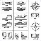 | ||||||||||||||
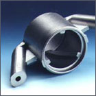
6. Keep in mind for sintering: Green and brown parts are not very strongand shrink noticeably during sintering. ■ Design with sufficient contact ■ area to support ■ Flat or contoured support ■ Avoid projections ■ Use a smooth support with low friction ■ If necessary, use feedstock supports ■ that shrink with the part (have to be ■ removed after sintering) ■ Adequate ribbing prevents sagging |
|


")